Cub Cadet 526 SWE Operator's Manual
Browse online or download Operator's Manual for Snow throwers Cub Cadet 526 SWE. Cub Cadet 526 SWE Operator`s manual User Manual
- Page / 28
- Table of contents
- TROUBLESHOOTING
- BOOKMARKS
- Op e r a t O r ’s Ma n u a l 1
- To The Owner 2
- Training 3
- Preparation 3
- CALIFORNIA PROPOSITION 65 3
- Maintenance & Storage 5
- Do not modify engine 5
- Notice Regarding Emissions 5
- Spark Arrestor 5
- Safety Symbols 6
- SAVE THESE INSTRUCTIONS! 6
- Assembly & Set-Up 7
- Top View 8
- Shear Pins 9
- Adjustments 10
- Auger Control 11
- Controls and Features 12
- Chute Clean-Out Tool 13
- Operation 15
- Maintenance & Adjustments 16
- Off-Season Storage 18
- Belt Replacement 19
- Drive Belt 20
- Friction Wheel Inspection 21
- Friction Wheel Removal 21
- Troubleshooting 23
- Replacement Parts 24
- Attachments & Accessories 25
- 27se c t i O n 11 — nO t e s 27
- CUB CADET LLC 28
- SNOW THROWERS 28
Summary of Contents
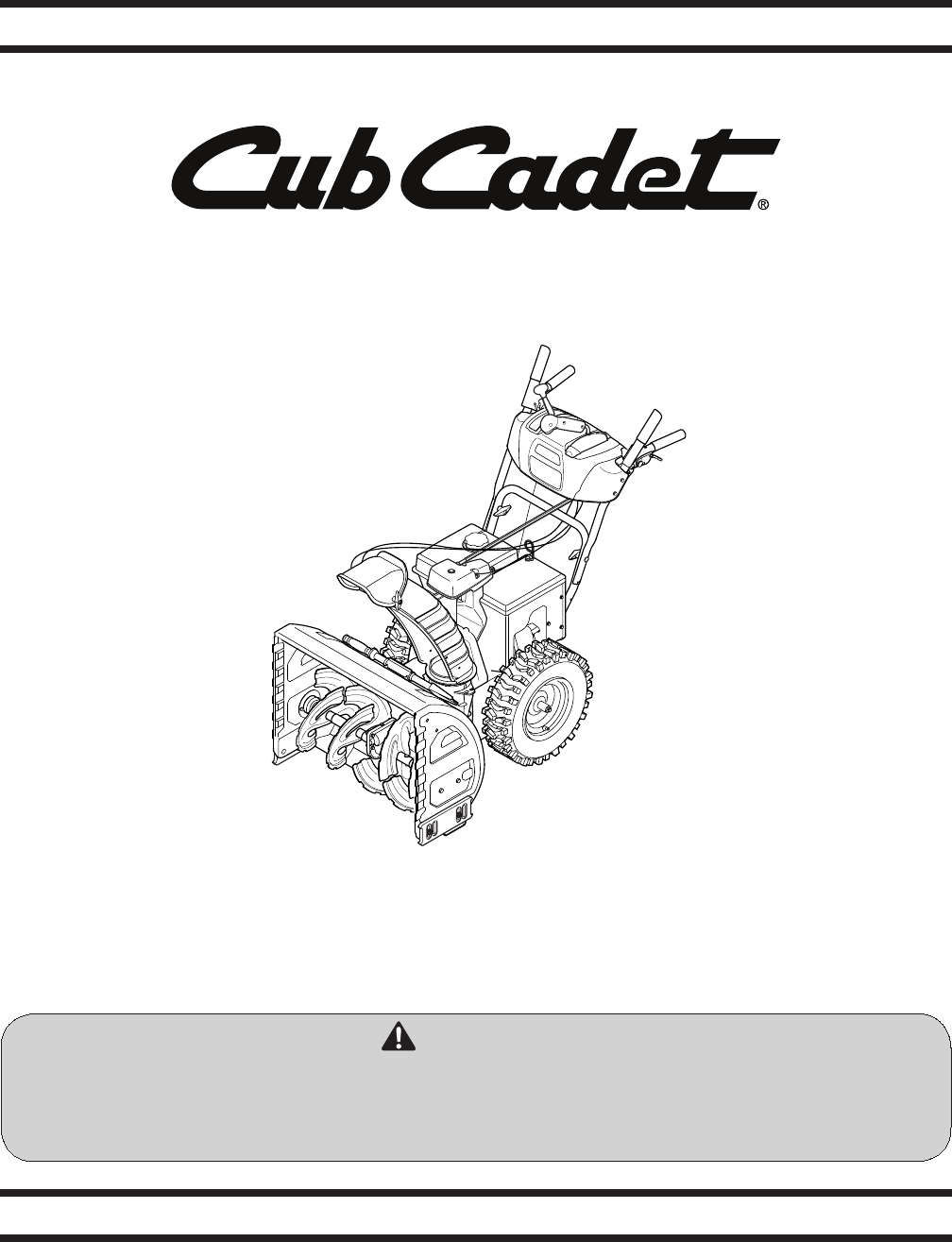
CUB CADET LLC, P.O. BOX 361131 CLEVELAND, OHIO 44136-0019Printed In USAOp e r a t O r ’s Ma n u a lSafe Operation Practices • Set-Up • Operation • Ma
Chute Clean-Out ToolThe chute clean-out tool is fastened to the top of the auger housing with a mounting clip and a cable tie at the factory. Cut the
Chute Assembly NOTE: Chutes on models with 4-Way Chute Control are controlled by the Chute Directional Control. See Fig. 4-1.The distance snow is thr
Snow thrower controls and features are described below and illustrated in Fig. 4-1. Shift LeverThe shift lever is located in the right side of the han
Auger ControlThe auger control is located on the left handle. Squeeze the control grip against the handle to engage the augers and start snow throwing
2-Way Chute Directional Control (if so equipped)The chute directional control is located on the left side of the dash panel.To change the direction in
Starting and Stopping the EngineRefer to the Engine Operator’s Manual packed with your snow thrower for instructions on starting and stopping the engi
MaintenanceEngineRefer to the Engine Operator’s Manual.Shave Plate and Skid ShoesThe shave plate and skid shoes on the bottom of the snow thrower are
Gear ShaftThe gear (hex) shaft should be lubricated at least once a season or after every twenty-five (25) hours of operation.Allow the engine to run
Drive ControlWhen the drive control is released and in the disengaged “up” position, the cable should have very little slack. It should NOT be tight.
Service719Belt ReplacementAuger BeltTo remove and replace your snow thrower’s auger belt, proceed as follows:Allow the engine to run until it is out o
Customer SupportIf you have difficulty assembling this product or have any questions regarding the controls, operation, or maintenance of this machine
20 se c t i O n 7 — se r v i c eRemove the belt from around the auger pulley, and slip the 7. belt between the support bracket and the auger pulley.
21se c t i O n 7 — se r v i c eBack out the stop bolt to increase the clearance between 6. the friction wheel disc and friction wheel. See Fig. 7-7.S
22 se c t i O n 7 — se r v i c eCarefully remove the hex nut which secures the hex shaft 5. to the snow thrower frame and lightly tap the shaft’s end
Troubleshooting823Problem Cause RemedyEngine fails to start Choke not in CHOKE position.1. Spark plug wire disconnected.2. Fuel tank empty or stale fu
Component Part Number and Description929-0071A Extension Cord, 110V954-04050 Auger Drive Belt (524 WE & 524 SWE)954-04260 Wheel Drive Belt (524
The following attachments and accessories are available for your Cub Cadet snow thrower. See your Cub Cadet dealer or the retailer from which you purc
Notes2611
27se c t i O n 11 — nO t e s
The limited warranty set forth below is given by Cub Cadet LLC with respect to new merchandise purchased and used in the United States, its possession
Important Safe Operation Practices23TrainingRead, understand, and follow all instructions on the 1. machine and in the manual(s) before attempting to
4 se c t i O n 2 — iM p O r t a n t sa f e Op e r a t i O n pr a c t i c e sSafe Handling of GasolineTo avoid personal injury or property damage u
5se c t i O n 2 — iM p O r t a n t sa f e Op e r a t i O n pr a c t i c e sClearing a Clogged Discharge ChuteHand contact with the rotating impell
6 se c t i O n 2 — iM p O r t a n t sa f e Op e r a t i O n pr a c t i c e sSafety SymbolsThis page depicts and describes safety symbols that may
AssemblyRemove all loose parts before assembling.Handle AssemblyPlace the shift lever in the Forward-6 position1. Observe the lower rear area of the s
Insert hex rod into chute control head. Push rod as far into 2. chute control head as possible, keeping the holes in the hex rod pointing upward. See
Insert the hex rod into the pinion gear below the joystick. 6. Make sure to line up the hole in the hex rod with the arrow on the pinion gear. See Fig
Related products and manuals for Snow throwers Cub Cadet 526 SWE
 (100 pages)
(36 pages)
(1 pages)
(100 pages)
(36 pages)
(1 pages)
© 2020, manymanuals.com. All rights reserved. | 1.828 s |
 Manymanuals.com
 Manymanuals.de
 Manymanuals.fr
 Manymanuals.it
 Manymanuals.pl
 Manymanuals.cz
 Manymanuals.es
 Manymanuals-pt.com
Comments to this Manuals